 Plymouth: The First Decade
Early 1930s Fuel Sending Unit
The parts book shows a different sending unit for each year and, of course, a different dash unit. However comparing notes with a number of other early Plymouth owners indicates that the resistance values for empty and full might be common across the years 1930 through 1938.
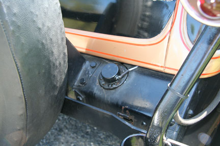
The sender unit is located in a visible location on 1930 through 1932 Plymouths. If you have a Plymouth from those years and visible authenticity is a consideration then you should consider repairing your original sender or looking for a duplicate of original unit. In my case the sender is not visible and the original sending unit had long since been replaced by a newer one that was not reading properly.
Physical Characteristics
Mechanical
The 1933 PD fuel tank is oval in cross-section with a height of 8 inches, front to back measurement of 15 inches and a exterior width of 37 inches. The shape is not exactly oval and the interior width is less than the exterior by a bit because of the overlap seam used to attach the ends to the body. The owners manual lists the capacity as 15 US gallons or 56.7 liters. Computing volume of an oval tank, it would seem the best guess for the interior dimensions would be 8"x15"x36.75".
Digression: On a sedan it is not clear to me that the tank can be filled completely as the lower edge of the fill tube is at just about the same height as the top of the tank. I personally have never been able to get 15 gallons into the tank, even when filling it after being totally drained. The coupe bodied cars have a longer fill tube and it should be easier to fully fill the tank.
The mounting flange for the fuel sending unit conforms to the five hole SAE standard that modern universal replacement fuel level sending units expect with regards to mounting holes but the holes are threaded for a smaller screw than comes with the new style universal sending units.
Electrical
The 1930 to 1938 Plymouths used a single wire system with the chassis providing a common “ground” for both the sender and the dash unit. On the dash unit the needle is attached to a small bar magnet. In the absence of any magnetic field gravity returns the needle to the empty position. The dash unit has two magnetic coils. Each is fed power from the ignition switch. One magnetic coil is wired to ground and attempts to pull the needle to empty. The other magnetic coil is attached to the tank sending unit. As more current flows through this coil it pulls the needle toward the full position. Because both coils draw power from the same source this unit is insensitive to variations in supply voltage. Basically this system uses the same principles are used as documented for the MG fuel gauges at http://www.mgaguru.com/mgtech/electric/fg_01.htm but without the wire wound voltage dropping resistor. The construction is quite crude compared to the MG system and it appears to be non-adjustable.
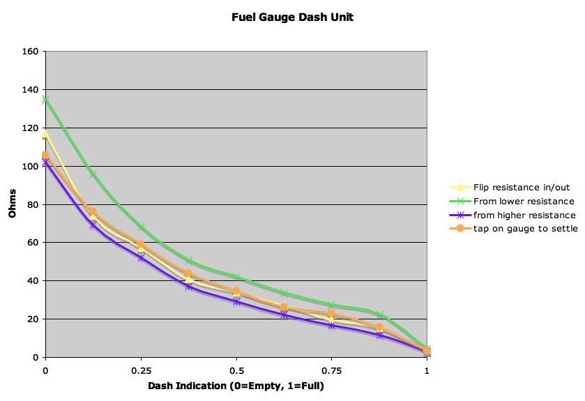 Placing a test set on the dash unit and
observing its operation with various resistance values shows
that there is some friction in the needle pivot: For any
given resistance value the needle will be lower (emptier
reading) if the value is approached from a higher resistance
and higher (more full reading) if approached from a lower
resistance. Snapping the power on or tapping on the
instrument panel both achieve similar results over most of
the range as both apparently overcome the friction in the
needle pivot. The notable exception is for values near
empty. The results for my particular dash unit are shown on
the graph to the right. The end points are approximately
3Ω to 4Ω for full and 106Ω to 117Ω
for empty.
Placing a test set on the dash unit and
observing its operation with various resistance values shows
that there is some friction in the needle pivot: For any
given resistance value the needle will be lower (emptier
reading) if the value is approached from a higher resistance
and higher (more full reading) if approached from a lower
resistance. Snapping the power on or tapping on the
instrument panel both achieve similar results over most of
the range as both apparently overcome the friction in the
needle pivot. The notable exception is for values near
empty. The results for my particular dash unit are shown on
the graph to the right. The end points are approximately
3Ω to 4Ω for full and 106Ω to 117Ω
for empty.
From correspondence with the owner of a 1935 PJ, I understand that his fuel level sending unit has 3Ω resistance for full and 128Ω resistance for empty. Checking the resistance range of a sender on a 1931 PA, the full value was between 15Ω and 20Ω with the empty value between 120Ω and 140Ω. In the case of the PA the resistance was very jumpy, possibly due wear on the resistance wires. Given errors in measurement and the age of the components it seems a reasonable guess that the early 1930s Plymouths used a common range of resistance values.
Survey the possibilities
 A number
of antique specialty suppliers claim to have appropriate
sending units but they are expensive ($85 and up) and the
illustrations and range of models they purport to fit (at
least for the $85 one I found) does not match the years that
my service manuals indicate reasonable. There is also a
source for “duplicate of original” sending units
but they are even more expensive. The “duplicate of
original” has a shellac coated cork float which might
have some issues with the alcohol in modern gasoline. Also
the photo of the “duplicate of original” does
not look like the originals. If you have a 1930 through 1932
Plymouth where the sender is visible this will look wrong.
Your best bet might be to repair the original.
A number
of antique specialty suppliers claim to have appropriate
sending units but they are expensive ($85 and up) and the
illustrations and range of models they purport to fit (at
least for the $85 one I found) does not match the years that
my service manuals indicate reasonable. There is also a
source for “duplicate of original” sending units
but they are even more expensive. The “duplicate of
original” has a shellac coated cork float which might
have some issues with the alcohol in modern gasoline. Also
the photo of the “duplicate of original” does
not look like the originals. If you have a 1930 through 1932
Plymouth where the sender is visible this will look wrong.
Your best bet might be to repair the original.
Inexpensive universal sending units are available in the following resistance ranges:
| Intended Application | Resistance Range |
|---|---|
| Stewart-Warner Gauges | 240Ω to 33Ω |
| Chrysler and Ford Gauges | 78Ω to 10Ω |
| General Motors Gauges | 0Ω to 90Ω |
| VDO Gauges | 10Ω to 180Ω |
Note that these universal units can be assembled with the resistor unit either way up so the empty/full resistance can be easily swapped. Unfortunately none of these units is an exact match to the range needed.
Digression: All these universal replacement units are basically the same: A float moves an arm that runs a wiper over a circuit board that has a set of contacts connected via thick or thin film screen printed resistive material. The design is more reliable than the old style with a resistive wire winding as the wear is on a contact specifically designed for it while the resistance material is separate from the contacts. On old style senders the wire would wear unevenly causing a number of issues. An Internet search turns up the fact that the circuit element is called a “fuel resistor card” and there are companies that make these to your specifications. So, in theory, we could simply have a batch of units made up with the appropriate “curve” for our old cars. However the sites I found require large orders.
Selecting A Sending Unit
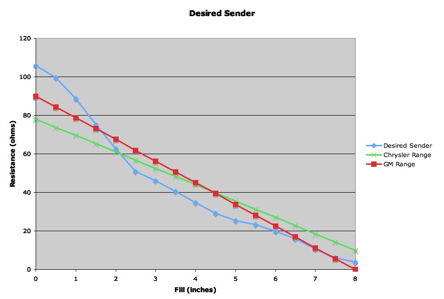
We are looking for a sending unit that has a reasonable fit to our desired “response curve“. For reasons that will become clear later, it is better if the resistance values are a bit low rather than a bit high. This rules out the Chrysler range as it would be difficult to make it read full. I assumed that the universal style replacements would have a linear response based on fill depth. The two best fits are show below. I decided on using the VDO part number 226008 which is listed for GM applications with a 0Ω to 90Ω range. This was not available from my local auto supply but was available for a reasonable price from several Internet based vendors.
| Inches Filled |
Gallons | Percent Full |
Desired Resistance |
|---|---|---|---|
| 0.0 | 0.0 | 0% | 106 |
| 0.5 | 0.4 | 3% | 100 |
| 1.0 | 1.1 | 7% | 89 |
| 1.5 | 1.9 | 13% | 75 |
| 2.0 | 2.9 | 20% | 63 |
| 2.5 | 4.0 | 27% | 51 |
| 3.0 | 5.1 | 34% | 46 |
| 3.5 | 6.3 | 42% | 41 |
| 4.0 | 7.5 | 50% | 35 |
| 4.5 | 8.7 | 58% | 29 |
| 5.0 | 9.9 | 66% | 25 |
| 5.5 | 11.0 | 73% | 23 |
| 6.0 | 12.1 | 80% | 20 |
| 6.5 | 13.0 | 87% | 16 |
| 7.0 | 13.9 | 93% | 11 |
| 7.5 | 14.6 | 97% | 6 |
| 8.0 | 15.0 | 100% | 4 |
An Issue With Ovals
 The five hole SAE flange is designed so
that the sending unit can only be installed one way.
Sending units seem to be listed as for “right
arm” or “left arm” applications. The
flange on the top of the 1933 Plymouth fuel tank is such
that the “right arm” and “left
arm” actually have the float arm in a fore/aft
configuration. If the sender has a top pivot point and
an arm long enough to reach the bottom of the tank then
it will not be able to swing all the way up.
The five hole SAE flange is designed so
that the sending unit can only be installed one way.
Sending units seem to be listed as for “right
arm” or “left arm” applications. The
flange on the top of the 1933 Plymouth fuel tank is such
that the “right arm” and “left
arm” actually have the float arm in a fore/aft
configuration. If the sender has a top pivot point and
an arm long enough to reach the bottom of the tank then
it will not be able to swing all the way up.
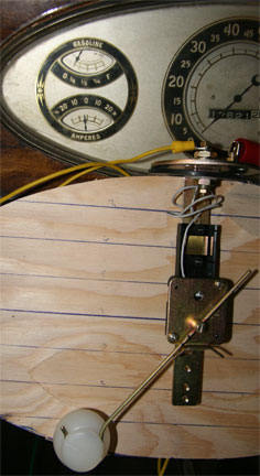
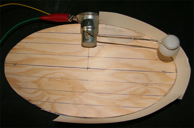
I suspected this but making a mock up quickly shows the issue. In the case shown to the left the float hitting the tank and the mismatch in response curves between the sender and the dash unit meant that the gauge never showed more than one half full.
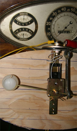
 Even a sender that pivots at the center of
the tank can have a problem, though not as severe. Since
the arm on the universal style sender can be set at any
arbitrary angle with respect to the SAE mounting flange
the unit will be mounted with the arm along the long
axis of the tank. This provides another half inch of
swing on both the top bottom.
Even a sender that pivots at the center of
the tank can have a problem, though not as severe. Since
the arm on the universal style sender can be set at any
arbitrary angle with respect to the SAE mounting flange
the unit will be mounted with the arm along the long
axis of the tank. This provides another half inch of
swing on both the top bottom.
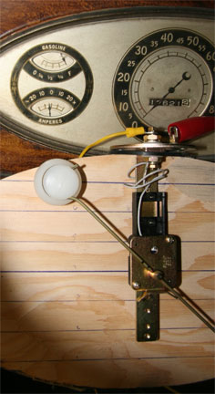
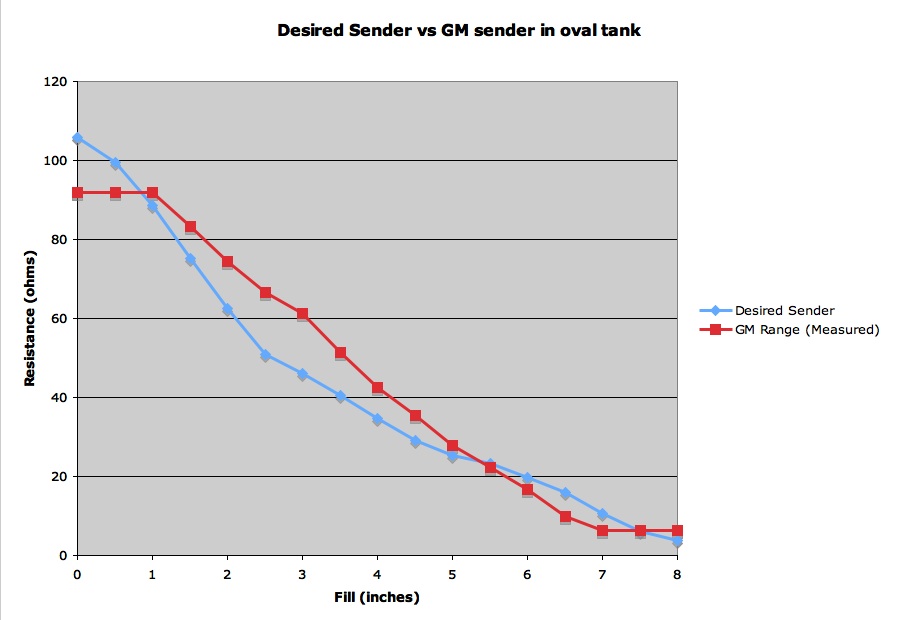
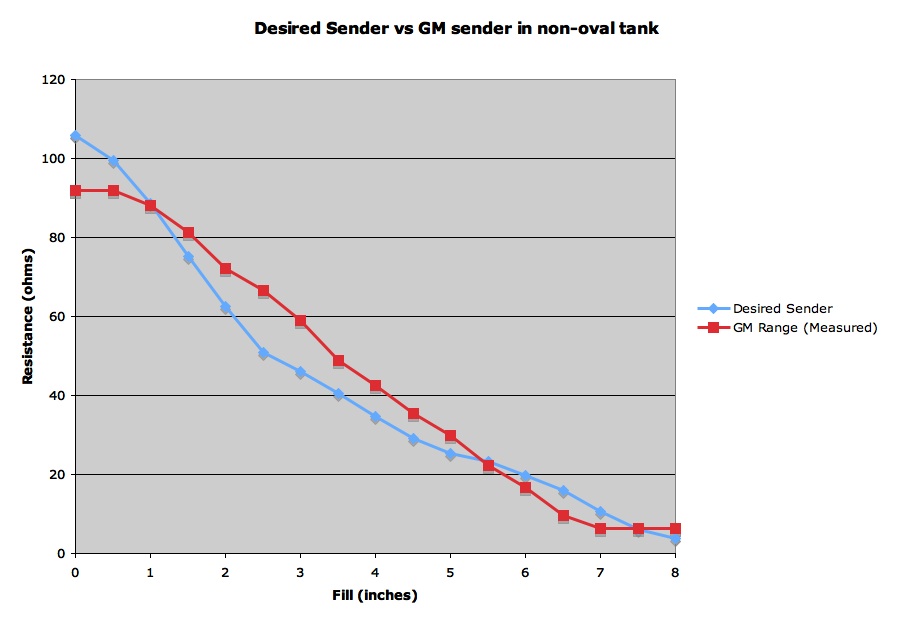
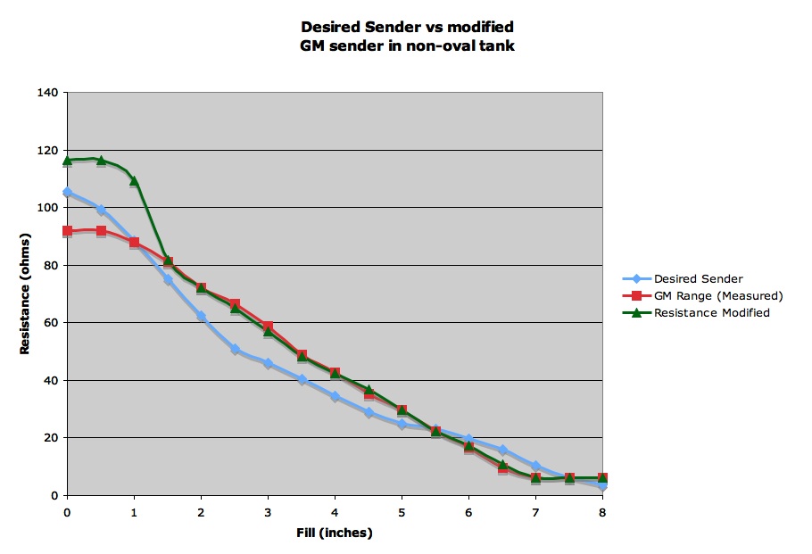
Measuring the actual response of the universal sender pointed out that I had neglected the physical size of the float when plotting out an ideal sender. It also showed the effect of an oval tank versus non-oval. In the plots below the oval (fore/aft) mounting does not match the desired response curve as well as the side to side mounting.
Modifying The Sender
 The sender could
probably be installed at this point however it will never
read empty which would be annoying.
The sender could
probably be installed at this point however it will never
read empty which would be annoying.
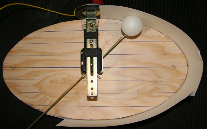
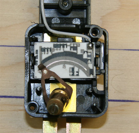
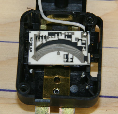
The sender works by having a contact attached to the arm that grounds one or more points on the “sender card” changing the resistance from the dash unit to ground. The resistors on the sender card a made up of resistive material which shows up as gray material in the photo to the right. The contact arm is place in the high resistance position which we are using for empty.
It is more useful to think of the resistive material as actually poorly conductive material. The more material that is there the lower the resistance as electrons can find more paths through it. By removing material we can increase the resistance.
Most of the response curve is a pretty good fit, we just need to increase the resistance by removing some material just above were the brass sweeper is located in the photo. A die grinder with a small wheel, taking small passes and measuring resistance often resulted in a butchered fuel sending card and a new response curve shown below.
The resistive material on the upper left of the card was removed first in the belief that it controlled the range of resistance over the last portion of the sweep. But, as it turns out that made no difference. The blurred area just above the sweep contact on the left are the result of removing resistive material with the die grinder and is what actually adjusted the sending unit’s range.
The Results
By The Numbers
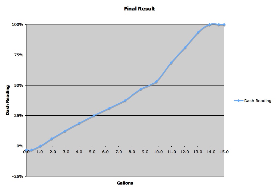 Using the
response curve of the dash unit, the shape of the fuel tank
and the response curve of modified the sending unit we can
predict how well the new sending unit will work. That is
shown to the right.
Using the
response curve of the dash unit, the shape of the fuel tank
and the response curve of modified the sending unit we can
predict how well the new sending unit will work. That is
shown to the right.
Using the tank mock up and this is verified by observing the dash unit at various sending unit float heights.
The results are not perfect. For example, there will be more than half a tank of gas when the dash gauge shows half. But the gauge will show full on full, empty on empty and be close enough in between to allow one to have a good feel for the amount of fuel in the tank.