
 Plymouth: The First Decade
This article was originally published in the Golden State Region, Plymouth Owners Club’s newsletter and is republished here with the permission of the author.
This page describes fitting a modern universal replacement fuel level sending unit to 1949 and early 1950s Plymouths. For fitting a modern one wire universal replacement fuel level sending unit to the early 1930s Plymouths see the other fuel sender page. If you have a two wire sending unit (1937-48 Plymouths) you will have to look elsewhere for help.
1950s Fuel Sending Unit
by Bob Amos
Have you ever gotten into you car and found the gas gauge to be dead? Sure you have. If you haven’t you some day will. And, this may be the answer to your problems. That is, if the sender has given up the ghost on you.
Let me start at the beginning of this adventure. About 2 years ago a customer of mine shows up at the shop with his ’53 Chrysler wanting a full rewire. Not being one to turn down a buck, I work up an estimate and he’s more than happy to leave the vehicle with me. I advise him that once the car is sporting a new harness we might find a few items that also need replacement. Well, as time passes and the cars harness is made up for us at YnZ wiring here in So. Cal. we start testing the various systems. Well, as luck would have it almost everything was on the Fritz!!! Including that all important gas gauge.
After testing results in the need for a sending unit the customer decides to provide the part himself. Something we frown on but begrudgingly allow this time. The unit does the trick.. well, only for a day or two. Ya see, he purchased the sender from one of the same suppliers that many of us use. To be honest, most vendors probably get their senders from the same original supplier so we cannot condemn the company that sold the part. Even though it was an $80 purchase. The owner now wants to provide another but this time an NOS unit priced at around $175. Well, being the kind hearted individual that I am (yeah right, like you guys are gonna believe that one) I allow this and in he comes with his proud purchase. The unit works well, so long as you don’t linger around ¼ tank. At this level the gauge tends to wander. So, when my own ’53 Plymouth’s fuel gauge drops dead on me I decide that there has to be a better, more reliable, way. And, what follows is the perfect, reasonably priced results.
Over at GT’s web site one of the guys suggested that we use a universal sender available from J.C. Whitney. It has the perfect range of 10 ohms to 78 ohms that our vehicles crave but it just will not fit very well. But, at a penny under $20 the price is certainly right. So, I go to the Whitney web site and have a “look see”. Part number ZX128525U. Well it looks good and I know the part as I have used these exact units in many off road and motor homes in the past. They are pretty rugged and are totally adjustable. (I might add at this point that this unit will only replace the single wire unit. If yours is a dual wire unit it will not fit your needs.)
Editor’s note: As of April 2013 it appears that J.C. Whitney no longer carries an appropriate sending unit. However this type of repair should work with other vendors version of a universal sending unit with a 10 to 78 ohm range.
Okay, so I now have the part and my old unit together. The problem is the top mounting disk. The one from the car is smaller and has absolutely no unsealed holes. This new unit has a number of holes for screws to be used as mounting points around the edges. At first I think about trimming it down to size and see how it will seal. But to tell you the truth, I am not comfortable with this. With over 40 years experience as a mechanic I feel that I am totally capable of combining the two units into one. So, with that said here goes.
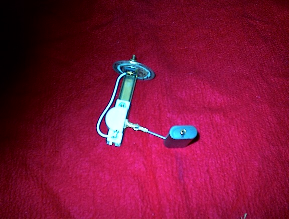
 You’ll notice that we have included step by step
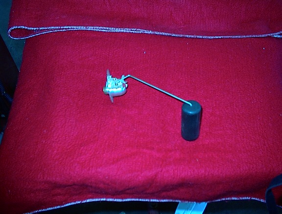
photos of the modification. Looking at photo #1 you will see
the stock unit as it looks when removed from the vehicle.
Notice the float and arm. It is attached to the rheostat
hidden under the dome on the mounting disk. What we will be
needed now is measuring the distance from the disk underside
surface to the bottom of the float. The float should be all
the way down when making this measurement. After taking the
measurement you are going to remove the float and arm. Now
cut the dome off and remove the stud that your vehicles fuel
gauge wire was attached to. In the end you will be reusing
the mounting disk and insulators that the stud goes through.
Discard the rest. What you should have now is what you see
in photo number 2.
You’ll notice that we have included step by step
photos of the modification. Looking at photo #1 you will see
the stock unit as it looks when removed from the vehicle.
Notice the float and arm. It is attached to the rheostat
hidden under the dome on the mounting disk. What we will be
needed now is measuring the distance from the disk underside
surface to the bottom of the float. The float should be all
the way down when making this measurement. After taking the
measurement you are going to remove the float and arm. Now
cut the dome off and remove the stud that your vehicles fuel
gauge wire was attached to. In the end you will be reusing
the mounting disk and insulators that the stud goes through.
Discard the rest. What you should have now is what you see
in photo number 2.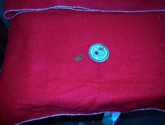
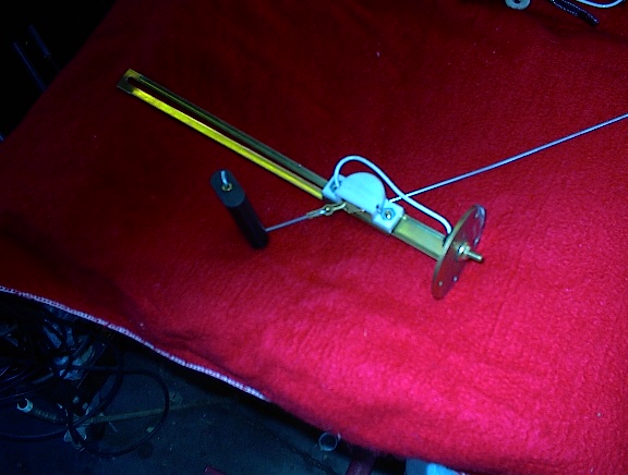 Next have a peek at photo number 3. Here you will see the
replacement unit. You are going to be salvaging the needed
parts from this. Disassemble the unit and photo number 4
will show what you will be using. Here you see the original
disk and insulator, also, you will see the new sender with
float, the insulators, nut and washer. Notice that the new
unit has been trimmed down to the proper size. I neglected
to take a photo of the unit before cutting. But what you are
going to do next is take the original sender disk and
insulator and marry this to the new unit. Looking at the
photo you will see the order in which everything will go
together. Look at the new sender and how the wire is
connected BEFORE you disassemble. You are going to be
reassembling this wire the same way on the modified
unit.
Next have a peek at photo number 3. Here you will see the
replacement unit. You are going to be salvaging the needed
parts from this. Disassemble the unit and photo number 4
will show what you will be using. Here you see the original
disk and insulator, also, you will see the new sender with
float, the insulators, nut and washer. Notice that the new
unit has been trimmed down to the proper size. I neglected
to take a photo of the unit before cutting. But what you are
going to do next is take the original sender disk and
insulator and marry this to the new unit. Looking at the
photo you will see the order in which everything will go
together. Look at the new sender and how the wire is
connected BEFORE you disassemble. You are going to be
reassembling this wire the same way on the modified
unit.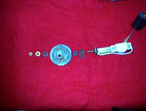
Now is time to trim the unit to size. Using the measurements taken earlier you are going to trim the long sender mounting slides to allow the sender to sit at the desired point. The pivot point of the new sender should be one half of the measurement. So, like my car, I had a total drop from disk to the bottom of the lowered float of 6 inches. Following these instructions, I set the pivot at the 3 inch mark. Yours may vary. Secure the screws on the back side of the new sender. Now trim the excess wire to fit.
 Next comes the float and arm. Set the float so that it
will travel through the same rage as your original. Mine,
again, was 6 inches. So, I set the float to be 6 inches from
disk to the base of the float when in the full down
position. Photo number 5 shows the finished unit.
Next comes the float and arm. Set the float so that it
will travel through the same rage as your original. Mine,
again, was 6 inches. So, I set the float to be 6 inches from
disk to the base of the float when in the full down
position. Photo number 5 shows the finished unit.
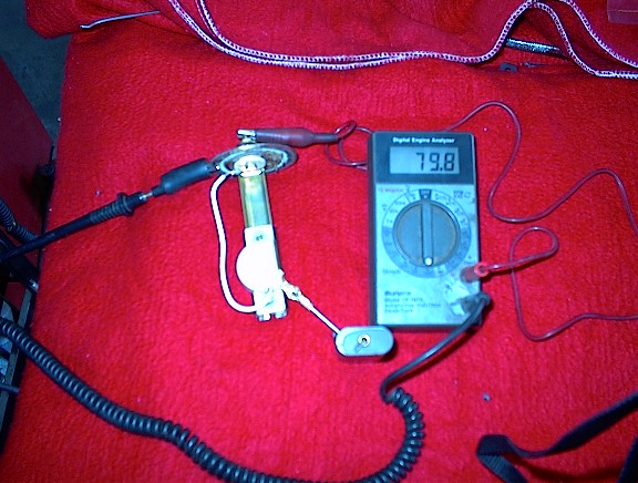
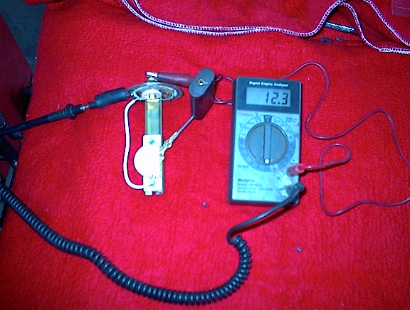
In photo 6 and 7 you can see that the gauge reads approx.
79.8 ohms in the empty position and approx. 12.3 ohms in the
full position. (On my ’54 wagon the unit would work in the
opposite direction. Not sure why they did this but just turn
the sender rheostat housing over to accomplish this.)
Before installing the newly finished sender, check the gasket and make sure it is not cracked or swelled up. If so, get yourself a new one. These are generally available from a good, real, parts house. I am not speaking of those fast serve chain stores. Once you have a good gasket, install the unit and secure the locking ring. Connect the wire and test the unit. If you prefer, you can attach a wire to the body of the unit and connect the other end to a good ground. With the key on raise and lower the float. Have someone check the dash gauge reading. It should travel through the range and read half when the float is at the mid travel point.
Pretty simple modification and this unit works much better than those repop units. Best of all they last much longer to boot.