
 Plymouth: The First Decade
USB Cellphone Charger
Background
If you tour with your old car you probably take along a cell phone. Or maybe a portable GPS based navigation unit. Nearly all new cellphones are setup so they can be charged off of a USB port. And, I think, a number of the navigation boxes can work that way too. This article covers how I put a USB charging system into my 6 volt positive ground car.
The USB power is +5v with respect to a negative ground. However the cellphones I have seen that can be charged off of a USB port are all housed in plastic and we can cheat and have the ground for the USB be the -6v to -8v we expect from our old car’s electrical system.
Schematic and Parts List
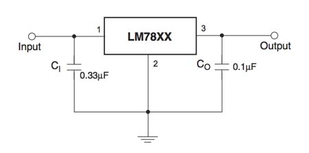 We will use a LM7805 which provides
5v regulated output at up to 1 amp. This, along with all the
other parts on this project, can be purchased at any
electronics store including Radio Shack. The circuit is
quite simple.
We will use a LM7805 which provides
5v regulated output at up to 1 amp. This, along with all the
other parts on this project, can be purchased at any
electronics store including Radio Shack. The circuit is
quite simple.
To account for the difference in ground convention we will attach our hot lead from the ignition switch to the “ground” on the LM7805 and the wire from our chassis will connect to the “input” pin.
- Plastic utility or project box. Electrically insulated as we don't want to short the heat sink to any metal part on the car. I drilled some holes in mine for ventilation.
- LM7805
- Heat sink for LM7805
- PC card to mount components into project box
- 0.33 µF capacitor
- 0.1 µF ceramic capacitor
- USB extension cable. We are going to cut the end off and use it for our connector. I happened to have a spare one laying around
- Fuse holder and fuse. I think a 1 amp fuse should be enough. The LM7805 will protect itself against shorted output so what we need to protect against is the “ground” of the USB touching any metal on the car. I used a 4 amp fuse which will protect the car but probably not the USB box.
- Mounting bracket. I used a “T” brace that was laying around my garage.
Assembling the beast
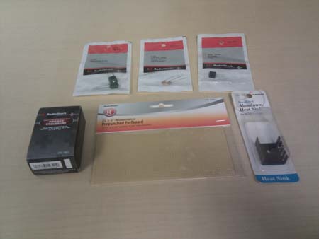 Here are most of the parts. Not much to say
other than to double check that your car ground is the
positive input to the device and that your power wire from
the car goes to the device ground. I found it easiest to tap
off my mounting bracket with a red wire (electrical
convention for supply voltage) and bring in a nice antique
looking black fabric covered wire from the ignition switch
(small electronics use black for ground which is different
from house wiring).
Here are most of the parts. Not much to say
other than to double check that your car ground is the
positive input to the device and that your power wire from
the car goes to the device ground. I found it easiest to tap
off my mounting bracket with a red wire (electrical
convention for supply voltage) and bring in a nice antique
looking black fabric covered wire from the ignition switch
(small electronics use black for ground which is different
from house wiring).
The USB cable, once cut open, reveals four wires. The red is for +5, the black is for USB ground and the other two are for data. If the two data wires are disconnected the USB standard requires that the USB device limit its power input to .5 amps which is well within the range of what the LM7805 can provide. If you connect the two data wires together then newer USB devices will detect that they are connected to a high power charger and may attempt to draw up to 1.8 amps which is more than the LM7805 can supply. So, connect the red wire to the LM8705 output, the black wire to the LM7805 “ground” (actually the hot wire from the ignition) and leave the two data wires disconnected.
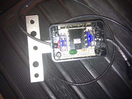 It all just fit in the smallest box that
was available in my local Radio Shack. I used two fuses, one
on the output as well as the wire from the ignition switch
only because the fuse holders came in a package of two.
It all just fit in the smallest box that
was available in my local Radio Shack. I used two fuses, one
on the output as well as the wire from the ignition switch
only because the fuse holders came in a package of two.
Final Result
Here is how the dash looks with the unit installed. Nothing
shows. 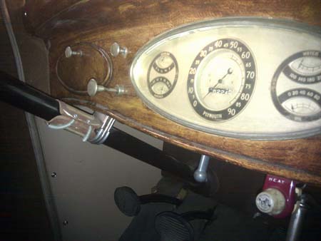
But if you look under the dash you will see it secured by
the U-bolt that braces the steering column.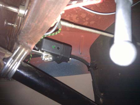
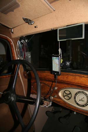 And now we are ready to go touring. The
smartphone can be used as a GPS navication device and a HD
movie camera as well as to make calls. I plan to make a
couple of “from the driver’s seat” test
movies to see if this suction cup mount will hold the cell
phone steady enough for shooting through the windshield.
And now we are ready to go touring. The
smartphone can be used as a GPS navication device and a HD
movie camera as well as to make calls. I plan to make a
couple of “from the driver’s seat” test
movies to see if this suction cup mount will hold the cell
phone steady enough for shooting through the windshield.
And, everything visible can be removed in seconds. And the box can be removed in just a couple of minutes as there is just two mounting nuts and one wire connected to the ignition switch.
Postscript and Update
The converter I wrote about above I still have installed in my car and is working well. However a thread on the discussion forum at the AACA web site had a link to a commercial product that is probably better. LightObject.com builds a tiny module that takes an input voltage of 3.5v to 10v and outputs upto 1.5 amps of regulated 12v power. Check it out. I probably would have tried using this had it existed or if I had known about it when I started my project. It uses a common ground between input and output so you will still need to isolate the output from the input. And you will need to regulate the 12v down to something your cell phone can use but there are lots of 12v to USB adaptors on the market.