 Plymouth: The First Decade
Electronic Voltage Regulation
Background
Most of the Plymouths of this era, indeed most cars of this era, were equipped with a “third brush regulated” generator. This generator acts as a constant current device with the output current depending on generator speed. For Plymouths, the maximum output was at about 25 MPH.
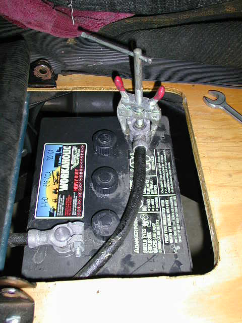
Ideally, the system should provide constant voltage, not constant current. For the third brush system to work the battery is used to keep the voltage from going too high or too low. A bad ground on the battery will cause system over voltage and result in burned out light bulbs. In any case the system voltage varies considerably and is generally low when the lights are on and you are traveling at speed.
If you adjust your generator so that you have sufficient output for high speed night driving, then you will be over charging during your day time tours. If you are adjusted for a low charging rate for day time tours, then you will be draining you battery at night and having dim lights too. So selecting the proper charging rate is difficult or impossible.
This difficulty in setting the charging rate optimally results in the battery being undercharged and sulfating or overcharged and boiling off electrolyte. There was a reason that “battery service” was a pretty big business for automotive garages in that day.
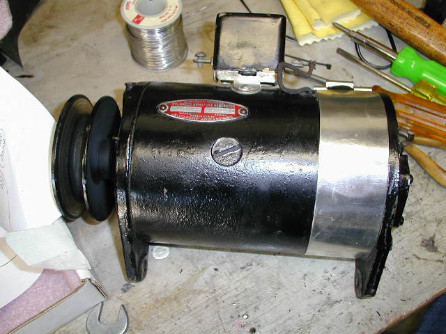
One solution is to install a voltage regulator. Since I am against visible modifications or modifications that can not be backed out easily this could be a bit of a problem: There is only one wire coming out of the generator, all field connections are internal to the generator. This rules out a conventional external voltage regulator.
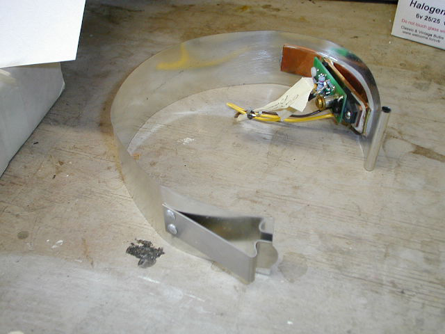
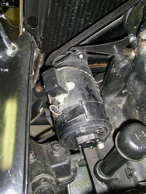
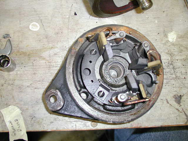
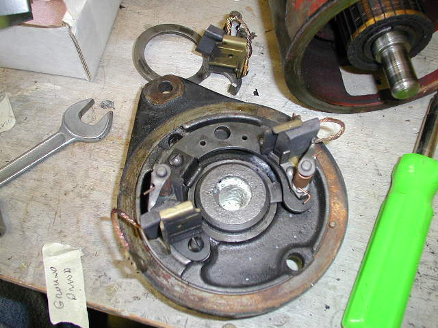
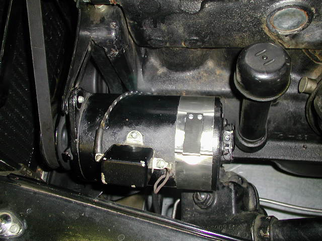
Fortunately, others have thought of this too and one hobbyist has designed an electronic voltage regulator that fits under the band that covers the brushes on early Delco-Remy generators.
I purchased such a regulator from James Peterson that was originally designed for a 1933 Buick. Jim did not guarantee this regulator because it was designed for a different car. Since the OEM (Delco-Remy) was the same for both Plymouth and Buick and since the diameter and brush holder opening dimensions matched for the two generators, I felt it was worth a try. This is page tells of the installation and initial impressions of this regulator.
Installation
| 1. |
|
| 2. |
|
| 3. |
|
| 4. |
|
| 5. |
|
| 6. |
|
| 7. |
|
| 8. |
|
| 9. |
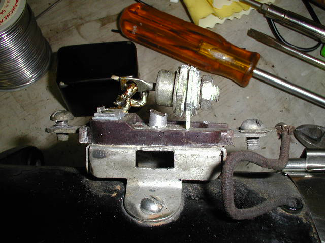
The regulator supplied by James Peterson has a small wire that should be cut if you are using a diode cut out. If you do not allow for that, then your voltage will be too low by the 0.8 volt drop across the diode and your battery will be under charged. |
| 10. |
|


Initial Impressions
It had been a couple of weeks since I had started the car. Under these conditions, it takes a little while to get gasoline up to the carburetor. So the starter had cranked for perhaps a total of 30 seconds. Once started the ammeter showed a high charging rate of 15 amps. I am not used to seeing it that high because if you set the third brush regulation that high you will boil the battery electrolyte.
As the engine warmed up the charging rate decreased smoothly. When the charging rate was about 10 amps I measured the voltage at the battery cable on the starter. It was 6.61 volts. I let the engine warm up at fast idle for a while then took a short drive. At the end of the drive the charging rate, which now seems to be speed independent, was about 5 amps. This seemed high, so I measured the voltage again and found 6.83 volts at the starter. This is the equivalent to 13.66 volts on a 12 volt system, which is a trifle below what is should be.
Since I had neglected to measure the battery electrolyte on my three year old battery, I do not know how much charge it should really take. But the system voltages seem about right.
A short night drive around the neighborhood followed. The ammeter show a slight discharge when at idle followed by a slight charging rate after accelerating up from idle. When turning off the lights after the drive the charging rate went up to 10 amps, indicating that the generator was not quite keeping up with the load. However, my “seat of the pants” method of determining night time voltage by the brightness of the dash lights indicated a big improvement.
The next day, I took an opportunity to make a half an hour drive with speeds of up to 50 MPH. This confirmed that the charging rate is now independent of road speed. It also showed that as the battery got full the charging rate decreased even more. At the end of the drive the ammeter was indicating about 2 amps charge.
Impressions update
Over July 5-7, 2001 we took a tour that covered about 250 miles. Much of it was over back roads at speeds of around 35 MPH. The ammeter showed a very slight charge during day light driving. The needle was barely off center, too little to even guess at the charging rate. I am sure it was much less than one amp. There was no evidence of over charging.
On the last day we finished off with about one and a half hours of night driving at 50 to 55 MPH. The ammeter showed zero. No discharge at all. When we arrived home and I got out to open the garage door I noticed that the head lights were still a nice white color showing proper voltage. There was no evidence of under charging.
This tour had exactly the type of driving that always frustrated me before. If I set the third brush regulation to be correct for the many hours of slow day time driving then it would be set much too low for high speed night driving. If I set it for maximum charging, then it would cook the battery during day driving. In addition, even at maximum output the third brush regulation was not sufficient to maintain full voltage while at high speed.
I am very pleased with how the system worked on this trip.