 Plymouth: The First Decade
Broken Temperature Gauge
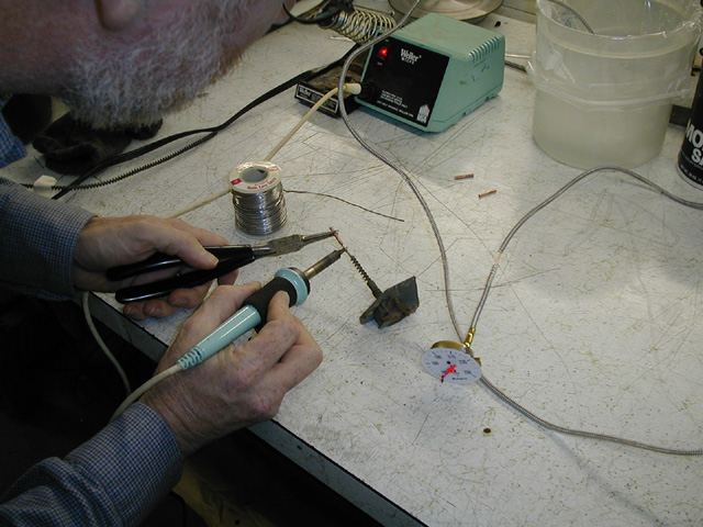
The temperature gauge is a “mechanical” unit consisting of a bulb with fluid (ether) mounted in engine head, a gauge head mounted in the instrument cluster on the dash, and a tube connecting the bulb to the gauge head. The gauge head is actually a pressure sensing unit.
In operation, the coolant in the engine head heats the working fluid in the sensor bulb. As the engine gets hotter the pressure in the bulb and tubing rises. The dash head unit simply reads the pressure on a scale calibrated in degrees Fahrenheit.
A common failure mode is for corrosion to lock the bulb in the engine head. The tubing is twisted off near the bulb when bulb removal is attempted. In this case, the gauge head unit is known to be working properly, the defect is in the tubing and in the loss of fluid from the sealed system.
For a more detailed description, a number of articles about the operation of this type of temperature gauge have appeared in Skinned Knuckles over the years. The earliest article I have is from the March 1984 issue.Replacement parts
Mechanical temperature gauges are still being manufactured and available in most auto parts stores. The goal of this procedure is to graft a new bulb (with fluid) and tube onto the old gauge head.
Find a gauge that has a spiral wound protective cover over the tube. There are some that use a plastic coating. While these can be made to work, they will not look correct. As of October 2004, it is possible to find a suitable donor gauge in California auto supply stores for about $15.
The Procedure
Caution: The working fluid in the gauge is ether, a highly flammable substance. Do not have any open flame near your work area. Do not use a torch for the soldering operations.
-
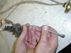
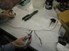
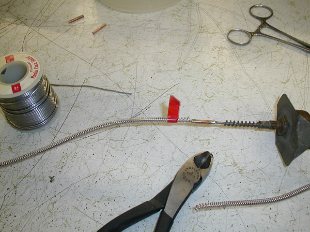
 Make up a
sleeve from some tubing. In this case the capillary on the donor
gauge had a slip fit into 1/16" inside diameter copper tubing
found at the local hardware store. The capillary on the original
gauge was slightly larger, so the 3/4" long sleeve was drilled
out halfway through to make a slip fit for the old capillary.
Make up a
sleeve from some tubing. In this case the capillary on the donor
gauge had a slip fit into 1/16" inside diameter copper tubing
found at the local hardware store. The capillary on the original
gauge was slightly larger, so the 3/4" long sleeve was drilled
out halfway through to make a slip fit for the old capillary. -
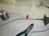
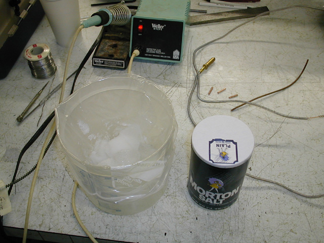
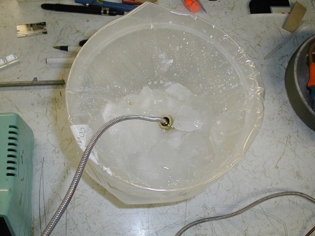
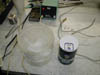 To keep the ether from
escaping we use some crushed ice and salt to create a “cold
bath” for the sensing bulb.
To keep the ether from
escaping we use some crushed ice and salt to create a “cold
bath” for the sensing bulb. -
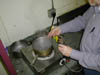
 And we might as well be
chilling the bulb while we do all the other preparation work.
And we might as well be
chilling the bulb while we do all the other preparation work. -
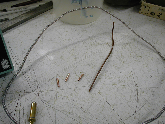
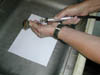 Trim the capillary tubing on the old gauge a couple of
inches from the gauge head.
Trim the capillary tubing on the old gauge a couple of
inches from the gauge head. -
 Make sure
that the tubing has not been closed off when trimming to length.
Make sure
that the tubing has not been closed off when trimming to length. -
 We might as well do
as much as we can before cutting open the donor gauge. So the next
step is to “tin” the capillary on the old gauge near the
cut. You don’t want to tin all the way to the cut as you
don’t want to encourage solder to fill the capillary
opening.
We might as well do
as much as we can before cutting open the donor gauge. So the next
step is to “tin” the capillary on the old gauge near the
cut. You don’t want to tin all the way to the cut as you
don’t want to encourage solder to fill the capillary
opening. -
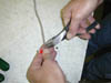
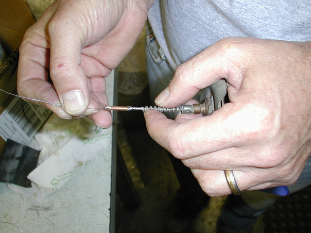
 Now we can attach the sleeve to the tinned capillary. In
this case we seated the capillary tubing to the limit that we opened
up the diameter by drilling.
Now we can attach the sleeve to the tinned capillary. In
this case we seated the capillary tubing to the limit that we opened
up the diameter by drilling. -
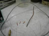
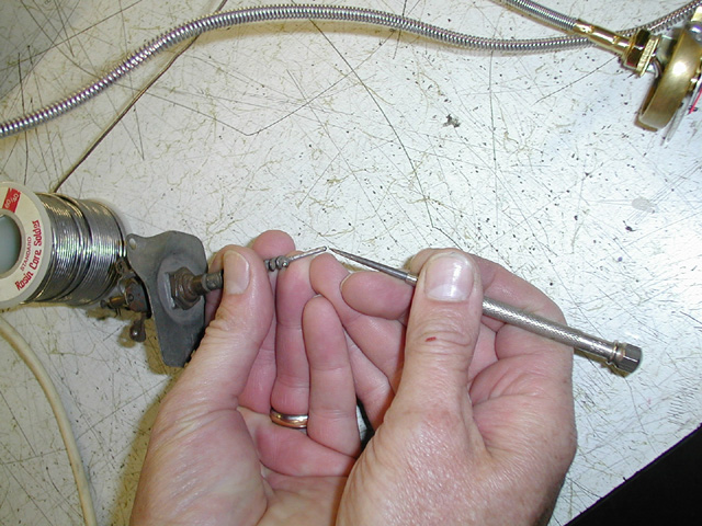
 Again we
want to make sure we have not closed off the capillary. A piece of
stiff wire small diameter can be used to verify that the capillary
is not clogged with solder.
Again we
want to make sure we have not closed off the capillary. A piece of
stiff wire small diameter can be used to verify that the capillary
is not clogged with solder. -
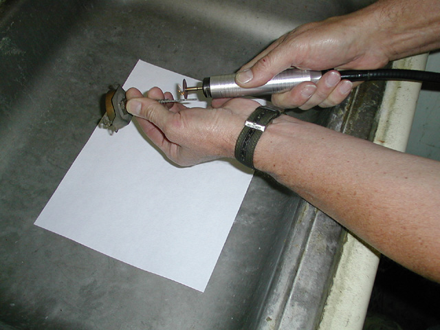
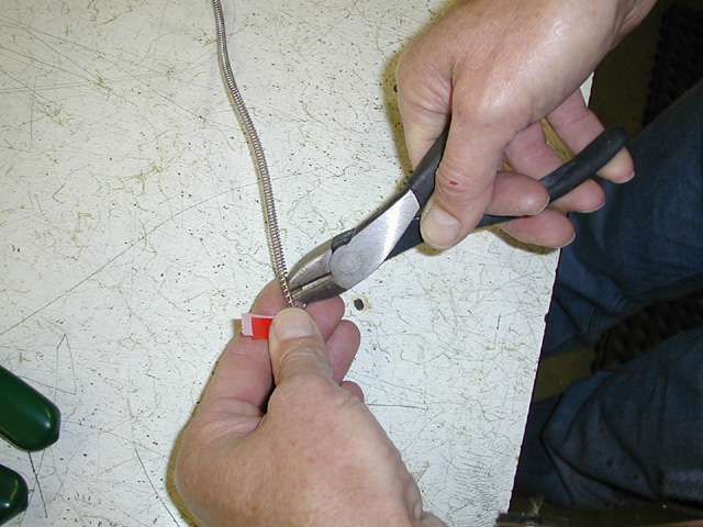
 Cut the protective spring on the donor gauge capillary
near the point marked for the length you need (indicated by the
tape).
Cut the protective spring on the donor gauge capillary
near the point marked for the length you need (indicated by the
tape). -
 In the
spirit of doing as much work as possible before breaking the seal on
the donor unit, we now tin the part of the capillary that will be
inserted in the sleeve.
In the
spirit of doing as much work as possible before breaking the seal on
the donor unit, we now tin the part of the capillary that will be
inserted in the sleeve. -
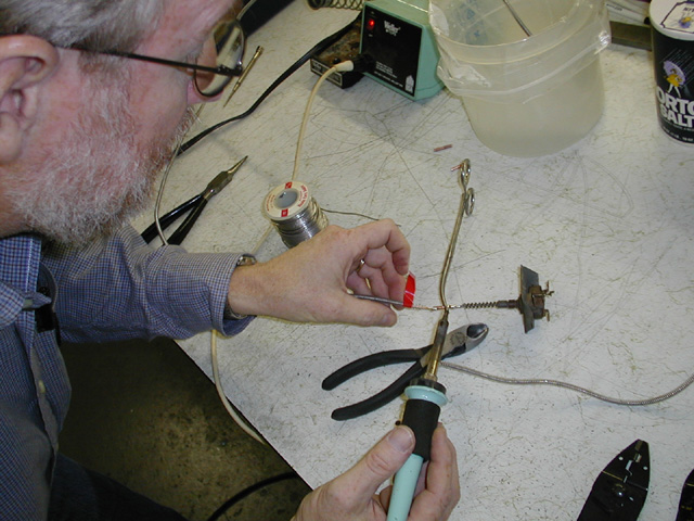
 Almost done! Verify that the sensor bulb is still in the
ice solution. Cut the capillary tubing, assure that the center is
open and now solder it into the sleeve.
Almost done! Verify that the sensor bulb is still in the
ice solution. Cut the capillary tubing, assure that the center is
open and now solder it into the sleeve. -
 Before removing the sensor bulb from the ice solution, double,
triple and quadruple check that you have a good solder joint with no
voids or other possible leaks on both sides of the sleeve. When you
are happy with your work it is time to check the function.
Before removing the sensor bulb from the ice solution, double,
triple and quadruple check that you have a good solder joint with no
voids or other possible leaks on both sides of the sleeve. When you
are happy with your work it is time to check the function. -
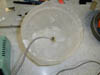
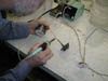
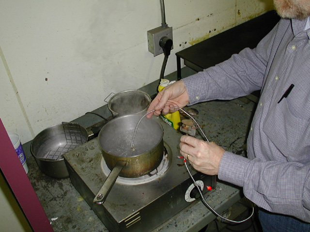
 Immerse the sensor
bulb in boiling water while observing the needle of the gauge. It
should move up to the 212° F mark. While observing the dial
mechanism, you might want to cycle the sensor bulb between the ice
solution and boiling water a few times to verify that nothing is
binding the movement. The gauge should now be restored to operation.
Immerse the sensor
bulb in boiling water while observing the needle of the gauge. It
should move up to the 212° F mark. While observing the dial
mechanism, you might want to cycle the sensor bulb between the ice
solution and boiling water a few times to verify that nothing is
binding the movement. The gauge should now be restored to operation.


Calibration
If the gauge does not read 212° F in boiling water you have two options:
- Note the error and live with it.
- Attempt to adjust the gauge head unit.
The gauge head is a Bourdon tube connected to the indicator by a linkage. The Bourdon tube is simply a flattened tube rolled into a coil. As pressure is applied the tube slightly unwinds. When the pressure is removed, the coiled tube returns to its original position.
Adjustment is made by bringing the sensing bulb to a known temperature by placing it in boiling water (212°F) then bending the linkage that connects the Bourdon tube to the indicator. Do not bend the Bourdon tube itself. [Chrysler 1953 page 70] States that it is possible to adjust the gauge if its reading is less than 30° different than the actual temperature.
If you have any doubts about the adjustment operation, then don't do it. You can buy replacement sensing bulbs and tubes at any auto supply store. Getting an original gauge dash head is a lot harder.
Installation
Avoid sharp bends or kinking the tubing when installing the repaired gauge.
Update
My original repair instructions were based on my 1977 repair of the gauge in my car and called for replacing the tubing at the gauge head. This current set of instructions is updated based on concepts presented in the April 2000 issue of Skinned Knuckles magazine. In an article by Bill Cannon a significant improvement is given. The improvement is in splicing the old tubing to the new tubing with the use of a sleeve. This allows you to work away from the gauge head and thus be less likely to damage it.
In the Restoration Forum of the June 2000 issue of Skinned Knuckles A. R. “Dick” Evans (“The Temperature Gauge Guy”) of Dunedin, Florida pointed out the safety issue of working with an open flame near the ether working fluid.
In general I don't make commercial endorsements on this web site. But I have to say if you repair or restore old cars a subscription to Skinned Knuckles is required.